


Experiments with motors
AC Motors ![]()
AC motors are also fairly simple to understand. They are a little trickier to make but will need single-phase or three-phase AC power to make them work. In the little diagrams above, we have a squirrel cage ac induction motor, a permanent magnet synchronous machine, and a synchronous motor. The inventor of the three-phase AC motor was Nikola Tesla, a pioneer in electromagnetism.
Here are some great sites which describe how AC motors work
and how to design them.
http://www.motorsoft.net/
http://www.magsoft-flux.com/ (shows a
Flux2D animation of the fields within a motor)
http://www.ece.umn.edu/users/riaz/animations/spacevectors.html
Great animations!
There are a couple types of basic AC motors you can build. They also make super science fair projects.
http://amasci.com/maglev/linmot.html
http://www.italtec.it/enkitmo.htm
A Very Simple AC Motor ![]()
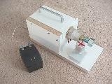
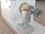
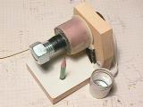
Here is a photo of a very simple eddy current AC motor I put together. I think this one wins the prize for the Simplest AC Motor you can make. It works great and is very easy to build. I found the original plans in a book titled: "Physics Demonstration Experiments" by Harry F. Meiners, Vol 2, Ronald Press Co., NY, 1970, LCCC #69-14674. With some experimentation, I found that the can spins faster when the nut is on the end of the bolt than when the nut is removed. What do you think will happen if the rotor is moved to the other side of the bolt? It consists of a coil mounted onto a 3/4" bolt. The coil is about 100' of 20AWG wire, on a form about 1.5" long, with a dc resistance of about 1.2 ohms, and an inductance of about 2.4mH as an air-core inductor. The voltage supplied to the coil is 19Vac from a plug-in transformer and supplies about 2.5Aac to the coil. The rotor is an aluminum film canister (today they use plastic, but you might still find a few of these around - ask your friends) with a dimple in the bottom of it, resting on a pencil. (I figured that the graphite in the pencil will lubricate the rotor.)
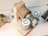
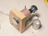
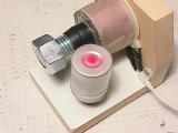
The eddy current motor on the left has two rotors, they spin in opposite directions. The set-up on the right shows a variac, multimeter, eddy current motor, and a calibrated strobe. With this, we could plot speed vs. voltage. We found that the rotor would spin about 1000 rpm with 120V applied to it. Can't keep it there for long, since the coil and bolt get real hot. On these two coils, a smaller diameter wire was used, so the dc resistance was about 11.2 ohms, and 24mH as an air-core inductor. With this, we could apply 120Vac to it and only 2 amps would be drawn.
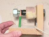
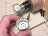
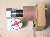
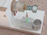
This shows the basic construction. The bolt is a 4" long 3/4-13 bolt, the wood is 3/4" thick. I put a small dimple into the bottom of the aluminum film canister so it would sit onto the pencil point. The red strips of tape helped with the strobe and looks cool as it spins. I found that the nut on the end of the bolt makes it go faster.
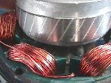
A Shaded Pole AC Motor
Here is a photo of a typical shaded pole motor. See the close-up of the notch in the laminations and the extra heavy winding of two turns creating the phase difference between the two sections of the laminations, giving the magnetic field a directional motion. The rotor spins CW as seen from the end with the screw on the shaft. Motors like this are used in thousands of applications.
Another Shaded Pole AC Motor
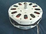
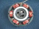
Here is a photo of a ceiling fan motor, also shaded pole, but with six windings instead of only one as seen above. The rotor laminations are skewed to provide smoother torque. The pole pieces with the windings have a slot in them to create a delayed flux, creating a direction for rotation.
A Universal Motor
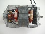
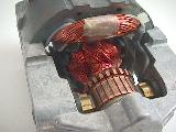
And here is a photo of a universal motor. It has brushes like a DC motor, but will operate on AC or DC.
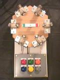
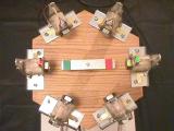
A 3-Phase AC Motor Demonstrator ![]()
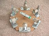
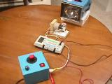
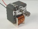
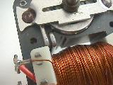
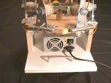
Here is a project my daughter is working on. It shows how a 3-phase AC motor works with a rotating magnetic field and a permanent magnet rotor, making it a synchronous AC motor. We have pushbuttons which allow the user to turn on any one of the pairs of opposite coils, in either a N-S or a S-N orientation. For example, the green button turns on the horizontal pair of coils in a S-N orientation. The yellow button turns on the horizontal pair of coils in a N-S orientation. On each coil is a bi-color LED to indicate the magnetic polarity of the coil when it is turned on. The power to the coils (each pair connected in parallel) is supplied by a 5v computer power supply. The coils draw about 4amps at 5Vdc each, so a supply with 23amps available is a great match. Each coil is mounted on a 3/4" bolt, attached to a hinge. This way, sets of coils can be folded down out of the way to show how a shaded pole motor works. The rotor is a bar of steel with a NIB magnet on each end. The rotor does oscillate a bit when going from coil to coil.
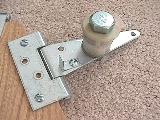
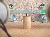
Here's more photos:
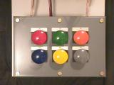
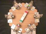


By pressing the colored buttons in the correct sequence, the rotor will follow the magnetic field in a clockwise fashion. The faster you go through the sequence, the faster the rotor will rotate. This shows that the speed of this motor is dependant on the frequency of the power applied to it. The higher the frequency, the faster it goes. At 60Hz, it would rotate at 1 revolution/cycle * 60 cycles/sec * 60 sec/min = 3600 revolutions per minute or rpm.
More construction details can be downloaded here.
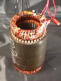
Three Phase AC Motor Stator
Industrial AC Motors
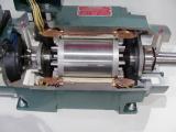
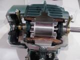
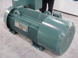
These are cut-aways of actual industrial three phase AC motors. They have different HP ratings, from 5hp, 2hp, 900hp. They are manufactured by Reliance Electric (used to be part of Rockwell Automation, now part of Baldor Electric).
Linear motors
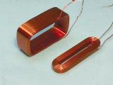
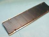
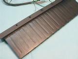
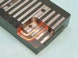
A linear motor is like an ac motor, but it is unwrapped and laid
out flat. The photos show parts of linear motors. Some have
flat coils and magnet sections, others are "T" shaped. Check www.anorad.com
for more info.
More information is available in these two excellent articles:
http://www-cdr.stanford.edu/dynamic/linear_engine/eng_ref/electric_motors/motion1.pdf
http://www-cdr.stanford.edu/dynamic/linear_engine/eng_ref/electric_motors/motion2.pdf
More on direct drive linear motors:
http://www.ifr.mavt.ethz.ch/publications/sprenger97a.pdf
http://www.ifr.mavt.ethz.ch/publications/sprenger98.pdf