


Experiments with electromagnets
DC Electromagnets
Description:
A DC electromagnet is simply a coil of wire connected to a DC voltage source. It can have an air core or an iron core.
Construction: ![]()
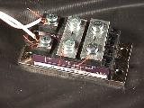
The construction would be the same as the AC electromagnet. The difference would be that instead of connecting it directly to the output of a variac, connect the output of the variac to a diode bridge (shown in the photo), and connect the coil to the DC output terminals of the diode bridge. To smooth out the DC output, a capacitor can be connected in parallel with the coil.
Demonstration:
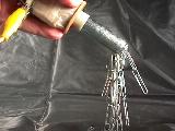
It can be shown how the DC electromagnet will pick up several paper clips. Next, turn the variac down to zero, to show how most of the paper clips fall off the end of the bolt. There may be a couple that hang on.
Conclusions:
It behaves like a permanent magnet as long as there is power applied to it. It's a magnet that can be turned on and off, and its magnetic strength can be varied as the voltage to it is varied. In fact, for the same voltage out of the variac, there will be more current flowing in the DC electromagnet than the AC electromagnet (no inductive reactance in the circuit), so it will be a stronger magnet!
The polarity of the magnetic pole at the end of the bolt does
not change like the AC electromagnet does. It will be either a North or a
South magnetic pole, depending on how it is connected to the output of the diode
bridge.
For a simulated diagram of the field around this electromagnet
without an iron core, look here.
For a simulated diagram of the field around this electromagnet with an iron core, look here.
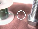
An Easy Electromagnet Experiment ![]()

Making an electromagnet isn’t hard, but understanding all of the variables involved can seem a bit overwhelming the first couple of times. Here’s an experiment that’s easy to make and do some measurements.
What you’ll need are the following:
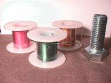
Set of magnet wire spools
(Radio Shack p/n 278-1345B)
200’
of 30 AWG wire
75’
of 26 AWG wire
40’
of 22 AWG wire
Steel bolt, ¾-13
thread, 2” long
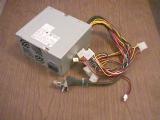
Computer power supply,
5V, good for 8A or more, or a large 6V lantern battery
Sandpaper, 100 to 200
grit, 2” square
BB’s, 3000 steel BB’s
in a plastic bowl
The steel bolt can be obtained from most hardware stores. The sandpaper can be picked up there, too.
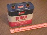
Computer power supplies, like those used for tower computers, are usually rated between 140W to 250W. They supply 5V at 8A or more, as well as +12V and –12V and -5V at much lower currents. We will want to use the 5V supply since that works much better than a battery. If you don’t have one, go to a computer store and ask if they have one that is broken, but the 5V supply still works. I got one for free that way. A new one is fine, but costs more. The +5V is usually the red wire. Find a connector with three of them and use all three in parallel for your supply. On the same connector should be two or three black wires as the common. Use them in parallel for your other connection. (+12V is usually the yellow wire, -12V is usually blue, and -5 is often white: don't use them.) If you want, you could use a 6V lantern battery, like the one pictured here. A smaller size battery will not be able to supply the current and will last for only a short time.
BB’s are steel balls about 4.5mm (0.177") in diameter that are used with BB guns. I bought a bunch of them at a sporting goods store. When you go, take a magnet with you to make sure that they are made of steel.
There are three key items that affect the design of an electromagnet, and each of them have several sub-items that need to be considered. They are the coil, the core, and the power source. Let's look at each one.
1. The coil
The diameter or gauge of the wire used for the coil.
The length of the wire used for the coil.
The number of turns of wire around the core.
The above parameters affect the dimensions of the coil: its inside diameter, outside diameter, and length. These dimensions, along with the size of wire used, determines the length of wire needed and the resistance of the wire.
2. The core
The size of the core.
The material used for the core.
Is the core going to be air, or will it be steel? Will the steel be laminated or solid? What shape will it have?
3. The power source
Is the power source DC or AC? If AC, what is the frequency? What is the duty cycle (how long is it on versus how long is it off)?
Why do all of these things affect the strength of the electromagnet? Because the one item that has the biggest effect is called the Ampere-turns. This is simply the number of amps of current flowing in the wire of the coil multiplied by the number of turns of wire there are around the core. So, length of the wire, its diameter, the size of the winding, and the source all affect either the amps that will flow or the number of turns that exist or both.
Let’s see how this works.
In the packet of magnet wire from Radio Shack, you get three spools. On one spool is 200 feet of 30 gauge of wire. It has a reddish color to it. It’s resistance is about 20 Ohms. With 5 Volts on the coil, the amount of current that would flow is equal to the voltage divided by the resistance, or 5/20 = 0.25 Amps. I figured there are about 800 turns of wire on the spool. So, the Ampere-turns is 0.20*800 = 200. This is saying that the strength of the magnet would be same no matter how you get the 200 Ampere-turns. For example, you could have 200 Amps, and 1 turn, or 1Amp and 200 turns, or any other combination. The effect would be the same in terms of the overall magnetic field created by this coil.
What happens when we look at the other spools? This table summarizes the data.
|
Length, feet |
Gauge, AWG |
Resistance, Ohms |
Voltage |
Current, I=V/R |
Number of turns |
Ampere-turns |
|
200 |
30 |
20 |
5 |
0.25 |
800 |
200 |
|
75 |
26 |
3 |
5 |
1.67 |
350 |
580 |
|
40 |
22 |
0.65 |
5 |
7.7 |
160 |
1230 |
This is saying, that for the same voltage connected to each of the coils, the coil using the 30 AWG wire would be able to pick up a certain number of BB’s. The coil using the 26 AWG wire would pick up about three times as many BB’s. And the coil using the 22 AWG wire would pick up about six times as many BB’s as the first coil, and two times as many BB’s as the second coil. We will use picking up BB’s as a way to compare magnetic field strengths. You could also use paperclips or nails, or staples, but BB’s work well and are fairly easy to count.
One other thing we need to keep in mind. When current flows through the wire, it creates heat. Will the coil get too hot? First, find out how many watts will be dissipated by the coil. For the third coil in the table above, the watts = I^2 * R = 7.7*7.7*0.65 = 38 watts. There needs to be enough surface area so that the watts/sq.in. is no more than 0.5. In this case, the watts/sq.in. works out to about 9.5, which is a lot more than 0.5! So, expect the coil to get hot and don't keep in on continuously. It's OK to run it for 10 seconds, then turn it off for 30 seconds to be able to cool.
Let’s try this out!
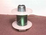
Take each coil and clean off about ¼” of the varnish on each end of the wire on each spool. Use the sandpaper to do this. Fold the sandpaper in half and pinch the wire between the paper and pull the paper straight off the wire. After a dozen times, you should start to see the copper color of the wire appear. This is very obvious on the red varnish and the green varnish wire. It’s harder to see on the clear varnish wire. Do this to both ends of the wire on each coil. One end sticks out of a small hole in the middle of the core. The other end will need to be unwound one turn from the outside of the coil. The reason for this is to be able to make a good electrical connection to the wire.
I kept the wire on the spools since it is neatly wound, and the hole in the middle of the spool is a good fit for a bolt.
Next, drop the ¾” bolt into the middle of the core of the spool of 30 AWG wire. This helps to concentrate the lines of magnetic field within the steel bolt instead of letting them disperse in the air.
Connect the coil to the 5V power supply. If you have a multi-meter that can measure the currents we anticipate in the table above, connect it between the power supply and the coil.
Now, pick up as many steel BB’s as possible, and hold them over a separate container, and disconnect the power supply from the coil, causing the BB’s to fall into the separate container. Reconnect the power supply, and again pick up as many BB’s from the first container as possible, and drop them into the second container. Do this for a total of 10 times. Now, count the number of BB’s in the second container and divide that number by 10. This will give you the average number of BB’s that electromagnet can pick up.
Next, do the same thing with the second spool of 26 AWG wire. Find out the average number of BB’s it can pick up. You will notice that this spool of wire will start to get a little warm.
Finally, do the same thing with the third spool of 22 AWG wire. This spool will get much warmer. If it gets too hot to hold, disconnect the power supply from the spool of wire for a few minutes to give it time to cool off. Again, your goal is to find out the average number of BB’s it can pick up.
With this data, compare the number of BB’s using each coil. How do the ratios of the numbers compare? Is it close to what we expected? Were you able to measure the current? Are they close to what we expected? If not, what could affect that value?
What else
could you do? You could wind the
wire onto a ¼” diameter bolt, and get a lot more turns using the same length
of wire. This would increase the
Ampere-turns of the electromagnet. Changing
the voltage of the power supply would also affect the strength, so, using the 6V
battery instead of the 5V power supply means more current, and thus more
Ampere-turns.
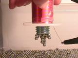
A Pair of Electromagnets on a Yoke ![]()
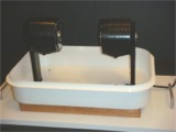
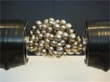
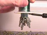
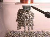
To make this, I took two DC electromagnets from a pair of 1000A DC contactors made by Cutler-Hammer. The electromagnets are about 4" in diameter, are 4" long, and have a 1" diameter soft iron core. I mounted them onto a steel "U" shaped yoke made of 1/2" thick, 2" wide steel, welded together, and bolted to the wooden base. I then put a plastic tray under them, made a AC/DC 2A supply for them using just a diode bridge fed from the 120V line. This gives us about 100Vdc for each electromagnet. They are wired to give a North pole facing a South pole.
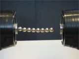
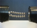
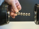
When it is turned on, you can stick a big bunch of steel balls between the two electromagnets. I use sizes that range from 1/4" to 3/4" to make it interesting. The photo on the right shows how these steel balls are temporary magnets since they act like a magnet when they are in a magnetic field and will stick to one another. The other photos show how they are like a bridge between the cores.
When you turn the electromagnets off - they all come crashing down! Kids love to play with this.
I got the idea for this from a magnet that I
saw at Technorama
which is like a radar magnet and costs about $6000. They use small steel
disks to stick to the magnets. They can't turn theirs off like I can,
though!

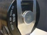
A DC Electromagnet ![]()

You can buy this DC electromagnet from Edmund Scientific, P/N X31132-00 for about $15. With it, you can experiment with seeing how much weight it can hold vs the voltage you apply to the coils. Connect the coils in series, connect them in parallel, use AC or DC voltage. Each coil is rated for 6Vdc. This electromagnet can lift and hold 40 pounds! Have fun!