


Experiments with electronics
Build your own Gaussmeter ![]()
Have you ever wanted to find out how strong a magnet really was, or how the strength of the magnetic field varied as you changed the distance from the magnet or the temperature of the magnet, or how well a shield placed in front of the magnet worked? Voltmeters are fairly inexpensive and easy to find, but where do you purchase a Gaussmeter (also known as a magnetometer). I built a hand-held Gaussmeter for measuring the polarity and strength of a magnetic field. It uses a linear Hall effect device and some op-amps and resistors and things from Radio Shack.
I will first describe a very simple, inexpensive Hall effect device Gaussmeter you can build for as little as $6. Then I will describe a Gaussmeter with a few more bells and whistles.
An inexpensive Hall effect Gaussmeter ![]()
Here is a parts list for the low-cost Gaussmeter:
Description |
Qty |
Radio Shack P/N |
Approximate Cost, each |
| 9v Battery | 1 | ||
| Battery Clips | 1 | 270-325 | 1.39/5 |
| 7805 Voltage Regulator | 1 | 276-1770A | 1.49 |
| Uncalibrated Hall Effect Device | 1 | (see text) | ~1.50 |
| IC Breadboard -or- Perf circuit board |
1 | 276-175 276-150A |
7.99 1.19 |
| Digital voltmeter, 3-1/2 digits | 1 | 22-802 | 24.99 or more |
First, you need a 9v battery. You can get them most anywhere.
Next is a battery clip to connect to the top of the battery. You get a package of 5 for $1.39.
The 7805 is a +5v regulator which takes the +9v from the battery and reduces it to +5v which the Hall effect device will need. It only costs about $1.49.
To purchase the uncalibrated Hall device, go to Hall Effect Devices .
You will need something to mount these parts onto - there are two possibilities. Use an inexpensive perf board and solder the parts to it, or use the breadboard and just plug the parts in - no soldering! Unless you've built electronic things before, I would recommend the breadboard since it is easy to use, easy to change, and can be used for other projects in the future. So that would cost $7.99.
You need a voltmeter for all the projects you're going to work on anyway, so I won't add that in for this project. There are different types available, and their cost goes up with features and functions. A basic one that will work well is noted in the table above.
There! Going with the perf board, it is only $6.07!!! Using the breadboard, only $12.87. (Battery and voltmeter not included.)
Now, how do you make it?
Connect the + (red) of the battery clip to the input of the 7805 (pin
1).
Connect the - (black) of the battery clip to the common of the 7805
(pin 2).
Connect the +5V input of the Hall device (pin 1) to the output of the
7805 (pin 3).
Connect the common of the Hall device (pin 2) to the common of the 7805
(pin 2).
Set the voltmeter to read 20Vdc max.
Attach the + of the voltmeter to the output of the Hall device (pin 3).
Attach the - of the voltmeter to the common of the 7805 (pin 2) or the
common of the Hall device (pin 2).
You are now ready to snap a battery onto the battery clip.
Here's a schematic of the circuit (using the 3503 or A1302 Hall-Effect Device):
With no magnet near the Hall device, measure and note the output
voltage reading. Call this V0. It should be about 2.50Vdc.
Now, with a magnet near the Hall device, you will see the output
voltage change. If it is a South pole, the voltage will increase. If it is a
North pole, the voltage will decrease. Call this voltage reading V1.
We will say that the sensitivity of the Hall device is 2.50mV/G as
found on their data-sheet. Call this k.
Therefore, the Magnetic Flux Density you are measuring from that magnet
can be calculated as:
B = 1000*(V0-V1)/k, in Gauss.
Please note that with a calibrated Hall device,
you would be given actual data measurements for the V0 value and for the k value.
For example, suppose you measured 2.48Vdc for
V0 and 1.32Vdc for V1. Then B = 1000*(2.48-1.32)/2.50 = 464Gauss, North pole
(because it is positive).
For another example, suppose you now measured
4.56Vdc for V1 with the same Hall device. Then B = 1000*(2.48-4.56)/2.50 =
-832Gauss, South pole (because it is negative).
See how easy that is? You can make your own plot using Excel so you don't have to calculate all the time. If you're taking measurements, just write down the output voltage and do the calculations later. You can simply use it to tell you if you have a North if the output voltage decreased from V0, or a South pole if the voltage increases from V0.
Here are some photos of this simple, inexpensive Gaussmeter.
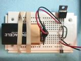
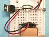
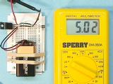
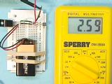
Photo 1 is an overall photo of the breadboard circuit. Let's look at the close-up in photo 2. The 9V battery is at the bottom, the 7805 voltage regulator is on the top left, the Hall device is on the top right. The red lead from the 9V battery goes to pin 1 of the 7805. The black lead from the battery goes to pin 2 of the 7805. The output of the 7805 (pin 3) is connected by a green wire to pin 1 of the Hall device. Pin 2 of the 7805 is connected by a black wire to pin 2 of the Hall device. Please note that the marking on the Hall device (giving its part number) is facing the camera. The voltmeter common (black) is connected to pin 2 of the Hall device. The voltmeter input (red) is connected to pin 3 of the Hall device. ( I got the voltmeter from a Home Depot store near here for about $20.) That's all there is! Great, or what?!
Photo 3 shows the voltage at pin 3 of the voltage regulator. Ideally it is 5.00 volts, but we measured 5.02, which is close enough.
Photo 4 shows the output of the Hall device when no magnet is nearby. Ideally it is 2.50 volts, but we measured 2.59. This would be our V0 as noted above. The Hall device I have here is an Allegro UGN3503U, with a sensitivity of about 1.3 mV/G. This is an older version of the A1302EUA-T.
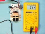
With a disk magnet sitting on top of the Hall device, the voltmeter is measuring 1.94 volts. This means that the Gauss measurement is 1000*(2.59-1.94)/1.3 = 500 Gauss, North pole.
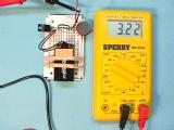
With the disk magnet flipped over, the voltmeter is measuring 3.22 volts. This means that the Gauss measurement is 1000*(2.59-3.22)/1.3 = -485 Gauss, South pole. You will notice that the placement of the magnet with respect to the Hall device is very critical, since the measurement varies across the surface of the magnet (as it is supposed to, being strongest at the edge, not the middle!).
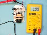
With a NIB magnet sitting on top of the Hall device, the voltmeter is measuring 0.99 volts. This means that the Gauss measurement is 1000*(2.59-0.99)/1.3 = 1231 Gauss, North pole.
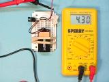
With the NIB magnet flipped over, the voltmeter is measuring 4.30 volts. This means that the Gauss measurement is 1000*(2.59-4.30)/1.3 = -1315 Gauss, South pole.
Now, the absolute value is not going to be correct since I don't have a calibration chart with this device, but the relative measurement will be as accurate as the Hall device, typically within 10 Gauss for the A3515 and the A3516 devices from Allegro. From the measurements, I know that the NIB is 1231/500 = 2.46 times stronger that the disk magnet! So, this gaussmeter will work well for measuring the variation of a magnet's flux density with respect to temperature very well!