


Experiments with electromagnets
Electromagnets
What is an electromagnet?
An electromagnet is simply a coil of wire. It is usually wound around an iron core. However, it could be wound around an air core, in which case it is called a solenoid. When connected to a DC voltage or current source, the electromagnet becomes energized, creating a magnetic field just like a permanent magnet. The magnetic flux density is proportional to the magnitude of the current flowing in the wire of the electromagnet. The polarity of the electromagnet is determined by the direction the current. The north pole of the electromagnet is determined by using your right hand. Wrap your fingers around the coil in the same direction as the current is flowing (conventional current flows from + to -). The direction your thumb is pointing is the direction of the magnetic field, so north would come out of the electromagnet in the direction of your thumb. DC electromagnets are principally used to pick up or hold objects.
When connected to an AC voltage or current source, the electromagnet will be changing its flux density as the current fluctuates. The polarity of the magnet will also change as the current reverses direction every half cycle. AC electromagnets can be used to demagnetize objects (like TV screens, audio tapes, vcr tapes) or to hold objects. However, due to the inductance of the electromagnet, the AC current that will actually flow will be reduced when compared to a DC voltage equal to the RMS value of the AC voltage feeding the electromagnet.
The key importance of an electromagnet is the ability to control the strength of the magnetic flux density, the polarity of the field, and the shape of the field. The strength of the magnetic flux density is controlled by the magnitude of the current flowing in the coil, the polarity of the field is determined by the direction of the current flow, and the shape of the field is determined by the shape of the iron core around which the coil is wound.
Here is an example of the yoke of a TV. It is made of two sets of electromagnets, perpendicular to each other, and mounts onto the neck of the TV tube. The current flowing through these wires controls the electron beam going to the screen of the TV, causing the beam to trace out a raster or series of horizontal lines, one after the other, from the top of the screen to the bottom, and then back to the top again for the next frame. This creates the picture we see on the TV screen. One set of windings moves the electron beam from left to right, the other set moves the electron beam from top to bottom.
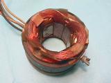
Winding a coil ![]()
Before you can start with the construction of an
electromagnet, you first need to figure out the following:
1. What will the core be made of
2. What magnetic flux density are you trying to achieve
3. How many turns will be required for this along with
4. How many amps will be flowing through the wire
5. How big will the wire have to be to handle the current
6. How much surface area will you have for cooling the coil
7. How big will the electromagnet be due to the above
8. What voltage rating will the insulation of the wire have to
withstand
9. What will be the inductance of the electromagnet
10. Obtain the core, wire, bobbin (form for the winding)
11. Wind the coil
12. Test the electromagnet
As you can see, there may be some times as you go through these steps that once you get an answer, you may have to go back a step or two and make some modifications, and recalculate. This is an iterative process.
To help, I use the following excel spreadsheet. Please feel free to use it. No warranties are implied. There may be errors, but I don't think so. There is definitely room for improvement. Coildata excel file. Simply save it to disk, and then open it. Fill in the data needed in the green boxes. It will calculate the length of wire in a coil, the resistance, and get an approximate inductance for an air core if you want to play with some numbers.
Here are some excellent sources for help in building an electromagnet or
coil.
http://www.ee.surrey.ac.uk/Workshop/advice/coils/index.html
A couple of things to keep in mind:
1. Use magnet wire with an enamel coating
2. If winding it onto a metal bar or bolt, first wrap the
metal with one or two layers of electrical tape so the winding does not short
out to the metal.
3. It takes time and care to do a clean, even winding.
4. After the first layer, wrap the layer with a thin piece of
paper, or another layer of electrical tape, to provide a smooth surface for the
second layer to lay on. Repeat this for each layer, or at least for every
three layers.
When working with electromagnets, I have found that having a variac (a variac is a variable autotransformer) has been a great help. This provides a variable AC voltage source. When you plug something into it, you can adjust the output voltage anywhere from 0 to 140Vac. I start with it at zero, then slowly bring it up, watching the current and voltage. This way, I have control over what happens if there is a problem or a limitation. By connecting a diode bridge to the output of the variac, you also get a variable DC voltage source. They are rated by how much current they can handle. Choose one that can handle 2 or 3 amps minimum. As the amp rating goes up, so does the price. They may cost about $100, not bad for a 10 amp unit with a built in ammeter (a meter that measures amps)!
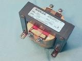
Transformers ![]()
A transformer is simply two electromagnets which are magnetically coupled together. There is electrical isolation between the two windings, but power can be transferred from one winding (the primary) to the other winding (the secondary) via the alternating magnetic field. They work on AC voltages. The ratio of the secondary output voltage to the primary input voltage is equal to the ratio of the number of turns in the secondary winding to the number of turns in the primary winding. (i.e., Vout/Vin = Nsecondary/Nprimary)
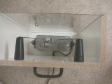
The photo on the left is a control transformer, and takes 230Vac in and drops it to 115Vac out for control circuits in industry. You can also turn it around and put 115Vac in and get 230Vac out. Transformers have a kVA rating which is the rated output Voltage times the rated output Amps divided by 1000. The one above is rated at 0.200kVA or 200VA. The two photos on the right show how to demonstrate the transformer action using two coils and the AC electromagnet from our electromagnet experiments.

This transformer was called a Sparker or Ignition coil, used to create the spark needed for the spark-plugs in cars from the '30s. It has a few turns for a primary winding, and lots of turns for a secondary winding. The mechanism at the end would open and close the circuit several times a second creating an AC like voltage on the primary (Since it was operated from a 12V battery, and transformers don't work on DC, a method was needed to create an AC type of voltage on the primary coil). The secondary has thousands of turns on it, creating a high voltage of around 30,000V which will arc about 10mm through the air.
Jacob's Ladder using a neon
sign transformer ![]()

This Jacob's Ladder uses a transformer which creates 15,000Vac on the secondary coil when 120Vac is applied to the primary coil. I built a box around the unit I show here. It has a Plexiglas front to keep curious fingers away from the wires. Be very careful with this!
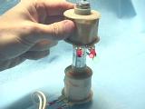
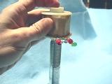
Battery Powered
Electromagnet capable of holding 500 lbs! ![]()
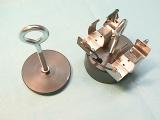
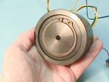

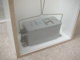
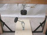
This is a lifting electromagnet from www.sciencefirst.com which is capable of holding 500lbs with just 2 D cell batteries! It costs about $55, but is quite a nice unit! It is their model number 20-035. They also have a slightly smaller electromagnet, model number 20-030, for about $47, which will hold 200lbs with just 1 D cell battery! The smaller unit is also available from ScientificsOnline (Edmund) as P/N 60-435.
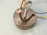
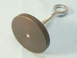
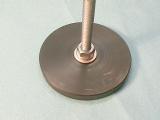
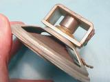
It is made of two parts - the yoke which also contains the coil, and the plate. The secret to the large holding force is that the plate and yoke are carefully machined so that there is no gap between them when they are placed together. It came with some excellent instructions on experiments you can do with it. However, I modified the larger unit a bit in order to make it easy to use on my wooden stand. Here's what I did.
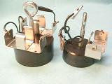
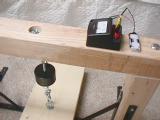
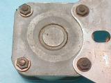
First, I removed the battery holders that came with it. Then I soldered longer wires to it, along with two banana plugs and a 9v battery clip in order to connect an ammeter in series with either a 2 cell AA battery holder or a 4 cell AA battery holder from Radio Shack. I also put a cable clamp on it so there wouldn't be any strain on the wires from the coil assembly. Then I put a longer eye bolt into the plate, and secured it with a flat and lock washer.
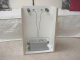
The Plank ![]()
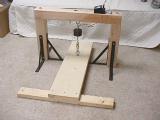
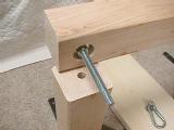
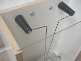
The wooden stand is made from a 4x4, 30" wide, and the two vertical supports are 18" tall each. The flat board or plank on the floor is a 2x10, and is 36" long. The cross piece at the end of the 2x10 is a 2x4, 30" long, to help stabilize the 2x10 when someone is on it. The photos show the construction details. The bolts on the horizontal 4x4 piece are 1/2" x 8" carriage bolts. I also have a string on the plate so that it won't crash to the floor or to the plank.
The demonstration calls for a volunteer who will walk the plank toward the electromagnet. When he is standing at the electromagnet, it is then holding his full weight. If someone (an anchor person) were to stand on the end of the 2x10 where it is attached to the 2x4 cross piece, and the volunteer were to stand on the 2x10 at the far end, then the electromagnet would be holding 1.5 times the volunteer's weight. (The anchor person will need to weigh at least half of the volunteer's weight, otherwise the anchor person will be lifted up, like a see-saw!) When the volunteer is on the plank near the electromagnet, then disconnect the battery and watch the plate of the electromagnet pull away from the yolk of the electromagnet, causing the volunteer to drop about 1.5" to the floor - proving that the batteries were able to convert enough chemical energy into electrical energy, the electromagnet's coil was able to convert the electrical energy into magnetic energy, and the electromagnet's yoke and plate were able to convert the magnetic energy into mechanical energy, in order to hold the volunteer's weight! Pretty amazing!
With four AA batteries, I know it can actually hold at least 300lbs. With two AA batteries, I know it can hold at least 225lbs, but less than 300lbs. I wanted to use AA batteries instead of D batteries since they were smaller and the effect is more dramatic! I call this demo "Walking the Plank"!
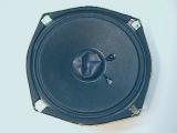
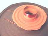
Speakers are made by placing a one layer coil of wire, wound onto a tube, into a magnetic field. The end of the tube is attached to the center of the paper cone of the speaker. When current is passed through the coil, a force is created on the coil, causing it and the tube to move within the magnetic field. When the current reverses direction, the coil and tube move in the opposite direction. This uses the Left Hand Rule.
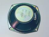
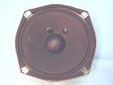
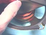
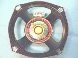
The photos above show a speaker and a magnet used for a speaker coil and its tube. The field is between the center post and the outer portion of the circular slit.
The speaker shown in the lower three photos will be dissected so you can see what the insides are like.
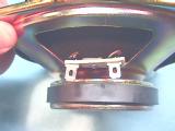
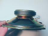
First, cut the wires going to the terminal strip. Then take a mat knife and carefully cut the cone around the edge. Let the knife follow the metal frame.

Next, you will need to hold the cone away as you carefully cut the inner paper disk, usually brown colored. You can then lift the cone and voice-coil assembly out of the magnet and frame. You can see how the magnet is made with a circular slit in it, where the center is a South pole, and the outside ring is a North pole (at least in this speaker). As current flows through the coil, it interacts with the magnet. The faster the current changes direction (the higher the frequency of the signal), the faster the cone moves in and out creating a higher frequency sound. The larger the magnitude of current, the farther the cone travels in and out of the magnet, the louder the sound. Connecting a battery to the speaker will cause the cone to pull in or push out a bit and stay there as long as the battery is kept connected. Reversing the battery connection will change the direction the cone moves (if it went out first, changing the battery around makes it go in the second time). Use a 1.5V battery for this test. This same effect is also demonstrated with the Fleming Left Hand Rule demo.
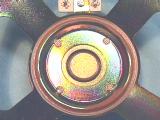
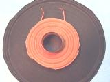
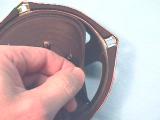
These are close-ups of the magnet, and the cone and voice-coil assembly. The voice-coil is the electromagnet, or solenoid. It is made with a very fine (small diameter) wire, with only two layers. It is then soldered to the flexible wires which you see on the left which attach to the terminal block. These wires are very flexible since the whole speaker cone goes in and out of the magnet in order to create the sounds.
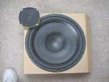
The speaker in the upper left is one like the 5" speaker cut open above. The larger speaker is a 15" woofer from Radio Shack. Place some small wooden or glass beads into the middle of the speaker cone, and attach a signal generator to the speaker terminals. As you vary the frequency and volume, the beads start to dance on the cone. Fun to watch!
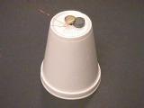
Have you ever wanted to make your very own, working speaker? Here's a great way to make one, and it's simple, too! I am grateful to Michael Gasperi for his suggestion and for this kit that he created.
The materials you will need are:

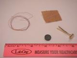
Take the wire, leave about 4" for a connection lead, and wrap the rest of it around the brad near its head. Keep the coil on the brad within 3/16" of the head as shown below. Again, leave about 4" at the end of the winding in order to make a connection to the coil.
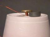
Now, place the magnet under the head (it will stick to the head of the brad) and press the brad into the bottom of the styrofoam cup. Separate the two tines of the brad and press them against the inside bottom of the cup as shown here.
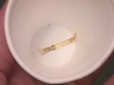
Finally, take the sandpaper and clean about 3/4" of each end of the wires from the coil in order to remove the enamel insulation so you can make an electrical connection to the coil. That's it! Just connect the two ends of the coil to a radio jack and you'll be able to hear the music.
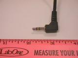
If you want, find an old, unused set of headphones and cut off the plug with some of the wire attached to it. Solder the pair of wire ends to the ends of the coil (one insulated wire to one end of the coil, the other wire of the pair to the other end of the coil). Then you can plug it in directly. (You could also buy a 1/8" mini plug with alligator clips from Radio Shack, p/n 42-2421, and clip that onto the ends of the coil.)
Here's a link for making a speaker out of a paper plate!
https://www.youtube.com/watch?v=Awef78YtWmc